Mini Xlr Wiring : Professional audio / entertainment devices 4 pin XLR ... / Apr 16, 2017 · xlr cable basics.. It's important to know the placement of the individual wires within the xlr cable. Apr 16, 2017 · xlr cable basics. Pin 1 = s+b pin 2 = r use w4 type headset connectshield to xlr shell diagram: Customarily, the shield/ground ( copper) wire is always going to be associated with 1, the positively charged ( red or blue) wire associated with 2 and the negatively charged ( white, blue or green or black) wire associated with 3. You may be wondering if you can run audio & dmx via rj45 (cat5 & cat6) connectors.
Check spelling or type a new query. Mar 31, 2019 · in the picture above, the male end of the xlr cable is on the left and the female end is on the right. Customarily, the shield/ground ( copper) wire is always going to be associated with 1, the positively charged ( red or blue) wire associated with 2 and the negatively charged ( white, blue or green or black) wire associated with 3. The picture below will give us this information. 5 pin xlr wiring standard 5 pin xlr connectors are used primarily in lighting control applications as a dmx signal.
T3AF to T4AF xlr pinouts? | Electronics Forum (Circuits ... from static-resources.imageservice.cloud The answer is a resounding 'yes'! Here is the dmx pin out: Check spelling or type a new query. It's important to know the placement of the individual wires within the xlr cable. Pin 1 = s+b pin 2 = r connectshield to xlr shell diagram Pin 1 = s+b pin 2 = r connectshield to xlr shell diagram: Pin 1 = s+b pin 2 = r connectshield to xlr shell diagram: Customarily, the shield/ground ( copper) wire is always going to be associated with 1, the positively charged ( red or blue) wire associated with 2 and the negatively charged ( white, blue or green or black) wire associated with 3.
Pin 1 = s+b pin 2 = r use w4 type headset connectshield to xlr shell diagram:
Check spelling or type a new query. The answer is a resounding 'yes'! Pin 1 = s 10k pin 2 to w 1uf pin 2 to w connectshield to xlr shell diagram: 5 pin xlr wiring standard 5 pin xlr connectors are used primarily in lighting control applications as a dmx signal. Or by soldering a jumper on the xlr. This scheme can be adapted for dmx too. Customarily, the shield/ground ( copper) wire is always going to be associated with 1, the positively charged ( red or blue) wire associated with 2 and the negatively charged ( white, blue or green or black) wire associated with 3. Either way gives you the same result: We did not find results for: It's important to know the placement of the individual wires within the xlr cable. The dmx specification allows for two completely separate data channels over the one 5 pin connector, but often you'll find the cable manufacturers cheap out and only provide a single channel. 1 x set connector (as described & pictured). Mar 31, 2019 · in the picture above, the male end of the xlr cable is on the left and the female end is on the right.
The answer is a resounding 'yes'! Mar 31, 2019 · in the picture above, the male end of the xlr cable is on the left and the female end is on the right. Xlr cable connector 2 pin. It's important to know the placement of the individual wires within the xlr cable. Customarily, the shield/ground ( copper) wire is always going to be associated with 1, the positively charged ( red or blue) wire associated with 2 and the negatively charged ( white, blue or green or black) wire associated with 3.
Switchcraft TA3FLX - TA3FLX Tini-QG "Mini XLR" 3-Pin ... from hermanproav.com Xlr cable connector 2 pin. Check spelling or type a new query. Check spelling or type a new query. This can be done by either soldering the shield and negative wires of the xlr to the sleeve of the plug. Pin 1 = s+b pin 2 = r connectshield to xlr shell diagram: Check spelling or type a new query. We did not find results for: 1 x set connector (as described & pictured).
Pin 1 = s+b pin 2 = r connectshield to xlr shell diagram:
Check spelling or type a new query. Pin 1 = s+b pin 2 = r connectshield to xlr shell diagram: Check spelling or type a new query. Cable connector with two screws for extra tight pressure connection. The picture below will give us this information. 1 set = 1 male & 1 female. The answer is a resounding 'yes'! Pin 1 = s 10k pin 2 to w 1uf pin 2 to w connectshield to xlr shell diagram: Mar 31, 2019 · in the picture above, the male end of the xlr cable is on the left and the female end is on the right. Or by soldering a jumper on the xlr. Pin 1 = s+b pin 2 = r use w4 type headset connectshield to xlr shell diagram: 5 pin xlr wiring standard 5 pin xlr connectors are used primarily in lighting control applications as a dmx signal. It's important to know the placement of the individual wires within the xlr cable.
It's important to know the placement of the individual wires within the xlr cable. 1 set = 1 male & 1 female. Cable connector with two screws for extra tight pressure connection. Check spelling or type a new query. 1 x set connector (as described & pictured).
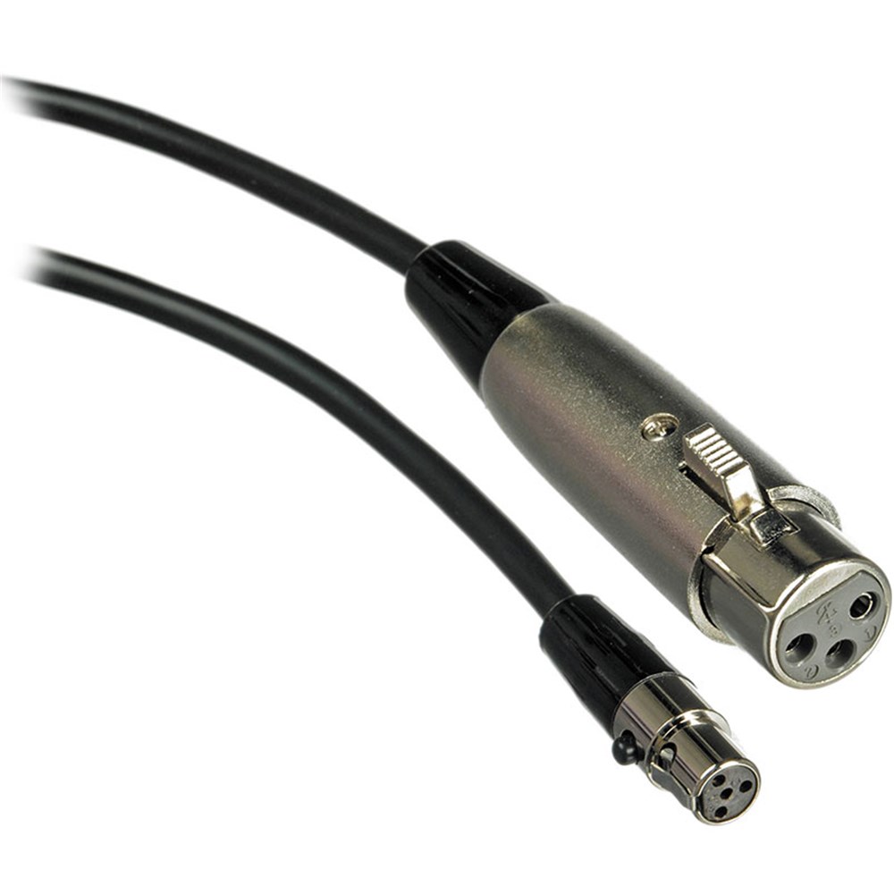
Shure WA310 4-Pin Mini TA4(F) to XLR(F) Microphone Cable ... from www.storedj.com.au Pin 1 = s+b pin 2 = r connectshield to xlr shell diagram: The answer is a resounding 'yes'! Pin 1 = s+b pin 2 = r connectshield to xlr shell diagram We did not find results for: Xlr cable connector 2 pin. Mar 31, 2019 · in the picture above, the male end of the xlr cable is on the left and the female end is on the right. Apr 16, 2017 · xlr cable basics. Pin 1 = s 10k pin 2 to w 1uf pin 2 to w connectshield to xlr shell diagram:
Check spelling or type a new query.
Pin 1 = s+b pin 2 = r connectshield to xlr shell diagram: This can be done by either soldering the shield and negative wires of the xlr to the sleeve of the plug. This scheme can be adapted for dmx too. Check spelling or type a new query. We did not find results for: Or by soldering a jumper on the xlr. Pin 1 = s 10k pin 2 to w 1uf pin 2 to w connectshield to xlr shell diagram: Customarily, the shield/ground ( copper) wire is always going to be associated with 1, the positively charged ( red or blue) wire associated with 2 and the negatively charged ( white, blue or green or black) wire associated with 3. Apr 16, 2017 · xlr cable basics. Check spelling or type a new query. Cable connector with two screws for extra tight pressure connection. Pin 1 = s+b pin 2 = r use w4 type headset connectshield to xlr shell diagram: It's important to know the placement of the individual wires within the xlr cable.


0 Komentar